The Hardware
The LDS (Laser Distance Sensor) module pulled from a 360 S7 robot vacuum.
The main PCB is marked Mtre1ss2018/12/13_V2.0. It has a spinning
laser assembly driven by a small DC motor through a 4:1 belt-and-pulley reduction,
a slip ring for passing signals to the rotating laser board, and a 6-pin
JST connector (J2) that was the original interface to the robot's RK3308 mainboard.
EG393 — motor driver IC · 220µF 10V cap — bulk decoupling on 5V rail · Inductor (331) — part of buck/boost converter · J2 header — 6 pins, only 3 used externally
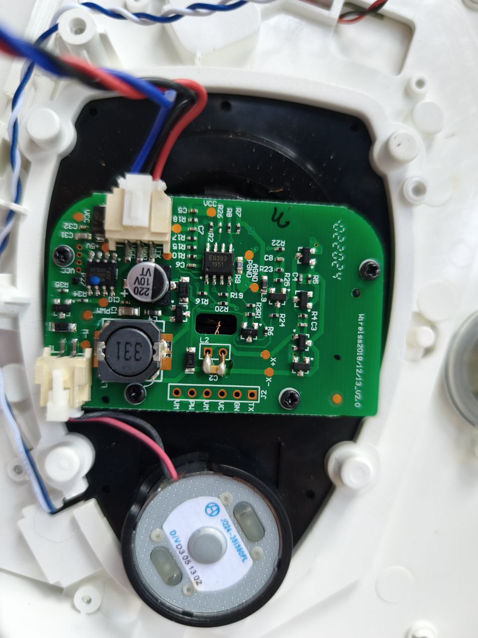
The J2 connector exposes only three wires to the outside world:
Pin 1  5V       — Power input (needs 5V, 5.2V from 18650 stepdown works)
Pin 2  GND      — Common ground
Pin 3  TX       — UART data out @ 115200 baud, 3.3V logic
Pin 4-6 NC      — Not connected externally
GPIO1 is the USB Serial/JTAG peripheral on ESP32-S3. Connecting any external signal to it will cause immediate instability. Use GPIO8 or any other clean pin instead.
The Problems — One by One
Reverse Engineering the Protocol
No datasheet exists for this LDS. The approach was pure serial sniffing — capture raw bytes, find the sync pattern, map fields by watching values change as the LDS was moved around and powered on/off.
Finding the Sync Bytes
The first hex dump immediately revealed a repeating pattern:
76 55 AA 03 08 A9 4D 6C DF 8D 01 19 95 01 D6 00
80 00 9B 01 07 8F 01 D9 8B 01 2B 87 01 19 88 01
58 FD E0 08 78 55 AA 03 08 A9 4D 36 E1 8D 01 51
00 80 00 00 80 00 00 80 00 0D 03 75 00 80 00 00
80 00 00 80 00 C1 E2 B6 13 55 AA 03 08 A8 4D FA
E2 BE 01 62 00 80 00 00 80 00 00 80 00 EB 02 D1
EC 02 A7 00 80 00 00 80 00 89 E4 66 59 55 AA 03
08 A8 4D C2 E4 00 80 00 00 80 00 8F 01 62 00 80
55 AA 03 08 repeating every ~34 bytes. Sync confirmed.
The 00 80 00 triplets are the no-return marker (0x8000 little-endian distance + 0 intensity).
The Motor Speed Trap
The most expensive mistake: assuming bytes 4-5 were angle. They're the motor
speed controller's PID output — it locks to exactly 0x4DA9 = 19881
once the motor reaches nominal RPM. Watch what happens during spinup and you see the truth:
[LIDAR] pkts:54893  pts:59   raw:[0-65535]      ← full sweep during spinup
[LIDAR] pkts:55936  pts:80   raw:[20927-65535]  ← still sweeping
[LIDAR] pkts:56979  pts:43   raw:[15394-19460]  ← converging
[LIDAR] pkts:58022  pts:17   raw:[19927-21406]  ← nearly settled
[LIDAR] pkts:61151  pts:2    raw:[19865-19883]  ← LOCKED at 199° forever
Bytes 4-5 = motor speed. Bytes 6-7 = actual angle. The correct field increments consistently by ~458 counts per packet, confirmed from four consecutive raw packets:
Packet 0: bytes[6:8] = 6C DF → mini360_angle = 162.36°
Packet 1: bytes[6:8] = 36 E1 → mini360_angle = 166.94°  +4.58°
Packet 2: bytes[6:8] = FA E2 → mini360_angle = 171.46°  +4.52°
Packet 3: bytes[6:8] = C2 E4 → mini360_angle = 176.02°  +4.56°
Full Packet Layout
| Bytes | Hex (example) | Field | Notes |
|---|---|---|---|
| 0-1 | 55 AA | Sync | Fixed magic bytes |
| 2-3 | 03 08 | Type + Count | Type=0x03, 8 samples |
| 4-5 | A9 4D | Motor Speed | PID output, locks at ~19881 at nominal RPM |
| 6-7 | 6C DF | Angle | Mini-360 format: (raw & 0x7FFF) − 0x2000, ×0.01 = degrees |
| 8-31 | 8D 01 19 ... | 8× Samples | dist_L dist_H intensity (3 bytes each). 0x8000 = no return |
| 32-33 | FD E0 | Checksum | CRC16 (not verified, ignored) |
The ESP32-S3 Parser
The final parser runs on UART2 (GPIO8 RX) at 115200 baud. A 4-byte shift-register hunts for the sync header. Once found, 30 remaining bytes are collected then parsed. The angle formula converts bytes 6-7 to degrees. Each valid distance reading is averaged into a 360-slot array indexed by integer degree.
// Confirmed packet layout from raw UART capture
// bytes 4-5 = motor speed (ignore)
// bytes 6-7 = angle, Mini-360 format
void parseLdsPacket(uint8_t* p) {
    uint16_t rawAngle = p[6] | (p[7] << 8);
    uint16_t masked   = rawAngle & 0x7FFF;

    if (masked < 0x2000) { parsedPackets++; return; }

    float startDeg = fmod((masked - 0x2000) * 0.01f, 360.0f);
    float arcStep  = 4.58f / (float)LDS_SAMPLES;  // ~4.58° per packet

    for (int i = 0; i < LDS_SAMPLES; i++) {
        uint8_t*  s    = &p[8 + i * 3];
        uint16_t  dist = s[0] | (s[1] << 8);

        // Filter: no-return, noise, out of range
        if (dist == 0x8000 || dist == 0x0080 ||
            dist == 0 || dist < 100 || dist > 6000) continue;

        float anglef = startDeg + arcStep * i;
        if (anglef >= 360.0f) anglef -= 360.0f;
        int slot = (int)anglef;

        // Running average per degree slot
        if (scanHits[slot] == 0) scanDist[slot] = dist;
        else scanDist[slot] = (scanDist[slot] + dist) / 2;
        if (scanHits[slot] < 255) scanHits[slot]++;
    }
    parsedPackets++;
}
The sync hunt uses a 4-byte shift register — efficient and robust against partial packet captures at startup:
while (LidarSerial.available() > 0) {
    uint8_t b = LidarSerial.read();
    if (!ldsSynced) {
        // Shift register — hunt for 55 AA 03 08
        ldsBuf[0] = ldsBuf[1]; ldsBuf[1] = ldsBuf[2];
        ldsBuf[2] = ldsBuf[3]; ldsBuf[3] = b;
        if (ldsBuf[0] == 0x55 && ldsBuf[1] == 0xAA &&
            ldsBuf[2] == 0x03 && ldsBuf[3] == 0x08) {
            ldsBufIdx = 4;
            ldsSynced = true;
        }
    } else {
        ldsBuf[ldsBufIdx++] = b;
        if (ldsBufIdx >= LDS_PKT_SIZE) {
            parseLdsPacket(ldsBuf);
            ldsBufIdx = 0; ldsSynced = false;
            ldsBuf[0] = ldsBuf[1] = ldsBuf[2] = ldsBuf[3] = 0;
        }
    }
}
The Result
After flashing the corrected parser, the Serial Monitor showed what we'd been working toward:
[KODA] BLE Advertising STARTED
[KODA] LiDAR:  GPIO8 RX, UART2, 115200

[LIDAR] pkts:100  pts:192  closest:211mm @105deg  raw:[41094-63693]=1-227deg
[LIDAR] pkts:192  pts:188  closest:211mm @105deg  raw:[41193-63970]=2-230deg
[LIDAR] pkts:283  pts:186  closest:211mm @105deg  raw:[41011-63909]=1-229deg
[LIDAR] pkts:374  pts:182  closest:211mm @105deg  raw:[40974-63746]=0-228deg
[LIDAR] pkts:648  pts:192  closest:208mm @112deg  raw:[41033-63799]=1-228deg
pts:192 — 192 unique degree slots populated per 350ms sweep. raw:[1-230deg] — genuine 229° angular coverage. closest:211mm — an iPad placed at exactly 210mm from the sensor. Accuracy within 1mm.
BLE Output Format
The firmware pushes scan data over BLE as compact binary pairs —
4 bytes per reading: [angle_L][angle_H][dist_L][dist_H].
Chunked into 176-byte BLE notifications to stay under MTU limits.
The Flutter app receives these and reconstructs the polar scan for rendering
and median filtering.
// On BLE notification received from LIDAR_CHAR_UUID:
void onLidarData(List<int> bytes) {
  for (int i = 0; i + 3 < bytes.length; i += 4) {
    final angle = bytes[i] | (bytes[i + 1] << 8);
    final dist  = bytes[i + 2] | (bytes[i + 3] << 8);
    readings.add(LidarPoint(angle: angle, dist: dist));
  }
  // Median filter per degree bucket for noise reduction
  updateScanMap(readings);
}
Lessons Learned
The motor speed field and the angle field looked identical in isolation — both were 2-byte little-endian values. Only watching them change over time (and across a power cycle) revealed which was which.
The LDS spin motor draws enough current on startup to brownout an ESP32 powered from USB alone. Always power the sensor from a separate rail with shared GND.
Vidicon's reverse engineering of the AliExpress mini LiDAR (github.com/Vidicon/Mini-360-Lidar) uses the same angle encoding formula — (raw & 0x7FFF) − 0x2000 — even though the packet structure differs. Cross-referencing helped crack the angle field.
The left USB port (native USB CDC) and external power rails fight each other on the ESP32-S3-WROOM devkit. Use the right USB port (CH343P chip) for Serial monitoring and power from the 5V header pin. Requires the WCH CH343 driver on Windows.
What's Next
This LiDAR is now one subsystem of Koda — a companion robot
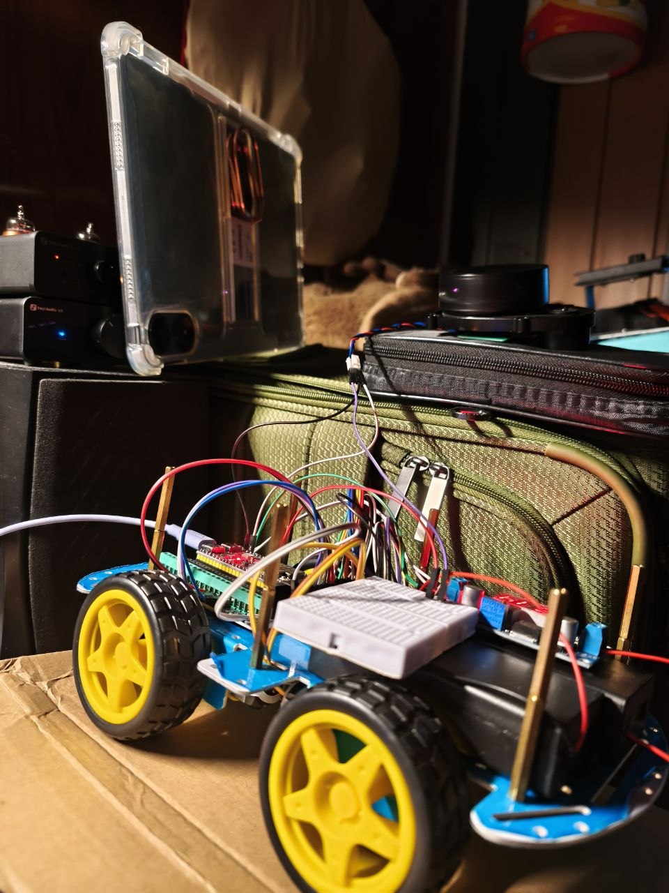
Next steps: implement SLAM on the S21 FE using the 230° scan arc, integrate wheel odometry from the motor encoders for dead reckoning between scans, and build the Flutter Brain Mode visualization that renders the live polar scan map.
The complete ESP32-S3 firmware — motor driver, BLE stack, LiDAR parser — is part of the Koda build. All three files (koda_firmware.ino, motor.h, commands.h) are self-contained and compile under Arduino IDE with NimBLE and ArduinoJson libraries.